Installation Instructions
Original Instructions
Compact I/O Expansion Power Supplies
Catalog Number(s) 1769-PA2, 1769-PA2K, 1769-PB2, 1769-PB2K, 1769-PA4, 1769-PA4K, 1769-PB4, 1769-PB4K
Topic | Page |
| Power Supply Components | 5 |
| Assemble the System | 6 |
| Mount the System | 8 |
| Connect the System | 10 |
| Wire the Power Supply | 11 |
| Replace the Fuse | 13 |
| Specifications | 14 |
| Additional Resources | 15 |
Compact I/O™ power supplies provide 120/240V AC and 24V DC power to modules, which you can place to the left or the right side of the power supply. As many as eight I/O modules can be placed on each side of the power
supply.
Summary of Changes
This publication contains the following new or updated information. This list includes substantive updates only and is not intended to reflect all changes. Translated versions are not always available for each revision.
| Topic | Page |
| Updated UK and European Hazardous Location Approval and IEC Hazardous Location Approval for UKEX and IECEx certifications | 3 |
| Removed power dissipation and derating information, and additional specifications that can be found in the CompactLogix Power Supplies Specifications Technical Data, publication 1769-TD008 | Throughout |
| ATTENTION: • If this equipment is used in a manner not specified by the manufacturer, the protection provided by the equipment may be impaired. • Read this document and the documents listed in the Additional Resources section about installation, configuration, and operation of this equipment before you install, configure, operate, or maintain this product. Users are required to familiarize themselves with installation and wiring instructions in addition to requirements of all applicable codes, laws, and standards. • Installation, adjustments, putting into service, use, assembly, disassembly, and maintenance are required to be carried out by suitably trained personnel in accordance with applicable code of practice. • In case of malfunction or damage, no attempts at repair should be made. The module should be returned to the manufacturer for repair. Do not dismantle the module. • This equipment is certified for use only within the surrounding air temperature range of 0… 60 °C (32…140 °F). The equipment must not be used outside of this range. | |||
Prevent Electrostatic Discharge | |||
| ATTENTION: This equipment is sensitive to electrostatic discharge, which can cause internal damage and affect normal operation. Follow these guidelines when you handle this equipment: • Touch a grounded object to discharge potential static. • Wear an approved grounding wriststrap. • Do not touch connectors or pins on component boards. • Do not touch circuit components inside the equipment. • Use a static-safe workstation, if available. • Store the equipment in appropriate static-safe packaging when not in use. | |||
North American Hazardous Location Approval | |||
| The following information applies when operating this equipment in hazardous locations. | Informations sur l’utilisation de cet équipement en environnements dangereux. | ||
| Products marked “CL I, DIV 2, GP A, B, C, D” are suitable for | Les produits marqués “CL I, DIV 2, GP A, B, C, D” ne conviennent | ||
| use in Class I Division 2 Groups A, B, C, D, Hazardous | qu’à une utilisation en environnements de Classe I Division 2 | ||
| Locations and nonhazardous locations only. Each product | Groupes A, B, C, D dangereux et non dangereux. Chaque produit | ||
| is supplied with markings on the rating nameplate | est livré avec des marquages sur sa plaque d’identification qui | ||
| indicating the hazardous location temperature code. When | indiquent le code de température pour les environnements | ||
| combining products within a system, the most adverse | dangereux. Lorsque plusieurs produits sont combinés dans un | ||
| temperature code (lowest “T” number) may be used to help | système, le code de température le plus défavorable (code de | ||
| determine the overall temperature code of the system. | température le plus faible) peut être utilisé pour déterminer le | ||
| Combinations of equipment in your system are subject to | code de température global du système. Les combinaisons | ||
| investigation by the local Authority Having Jurisdiction at | d’équipements dans le système sont sujettes à inspection par | ||
| the time of installation. | les autorités locales qualifiées au moment de l’installation. | ||
| WARNING: Explosion Hazard – • Do not disconnect equipment unless power has been removed or the area is known to be nonhazardous. • Do not disconnect connections to this equipment unless power has been removed or the area is known to be nonhazardous. Secure any external connections that mate to this equipment by using screws, sliding latches, threaded connectors, or other means provided with this product. • Substitution of components may impair suitability for Class I, Division 2. | AVERTISSEMENT: Risque d’Explosion – • Couper le courant ou s’assurer que l’environnement est classé non dangereux avant de débrancher l’équipement. • Couper le courant ou s’assurer que l’environnement est classé non dangereux avant de débrancher les connecteurs. Fixer tous les connecteurs externes reliés à cet équipement à l’aide de vis, loquets coulissants, connecteurs filetés ou autres moyens fournis avec ce produit. • La substitution de composants peut rendre cet équipement inadapté à une utilisation en environnement de Classe I, Division 2. | ||
2 Rockwell Automation Publication 1769-IN028J-EN-P – August 2022
UK and European Hazardous Location Approval—1769-PB2, 1768-PB2K, 1769-PB4, and 1769-PB4K
| The following applies to products marked II 3 G: • Are Equipment Group II, Equipment Category 3, and comply with the Essential Health and Safety Requirements relating to the design and construction of such equipment given in Schedule 1 of UKEX Regulation 2016 No. 1107 and Annex II of EU Directive 2014/34/EU. See the UKEX and EU Declaration of Conformity at rok.auto/certificationsfor details. • The type of protection is II 3 G Ex EC IIC T4 Gc according to EN IEC 60079-0:2018, EXPLOSIVE ATMOSPHERES – PART 0: EQUIPMENT – GENERAL REQUIREMENTS, Issue Date 07/2018 and CENELEC EN IEC 60079-7:2015+A1:2018, Explosive atmospheres. Equipment protection by increased safety “e”. • Comply to Standard EN IEC 60079-0:2018, EXPLOSIVE ATMOSPHERES – PART 0: EQUIPMENT – GENERAL REQUIREMENTS, Issue Date 07/2018, CENELEC EN IEC 60079-7:2015+A1:2018 Explosive atmospheres. Equipment protection by increased safety “e”, reference certificate number DEMKO 12 ATEX 1116807X and UL22UKEX2516X. • Are intended for use in areas in which explosive atmospheres caused by gases, vapors, mists, or air are unlikely to occur, or are likely to occur only infrequently and for short periods. Such locations correspond to Zone 2 classification according to UKEX regulation 2016 No. 1107 and ATEX directive 2014/34/EU. • May have catalog numbers followed by a “K” to indicate a conformal coating option. | |
| IEC Hazardous Location Approval—1769-PB2, 1768-PB2K, 1769-PB4, and 1769-PB4K | |
| The following applies to products with IECEx certification: • Are intended for use in areas in which explosive atmospheres caused by gases, vapors, mists, or air are unlikely to occur, or are likely to occur only infrequently and for short periods. Such locations correspond to Zone 2 classification to IEC 60079-0. • The type of protection is Ex EC IIC T4 Gc according to IEC 60079-0 and IEC 60079-7. • Comply to Standards IEC 60079-0, Explosive atmospheres _ Part 0: Equipment _ General requirements, Edition 7, Revision Date 2017, IEC 60079-7, 5.1 Edition revision date 2017, Explosive atmospheres – Part 7: Equipment protection by increased safety “e”, reference IECEx certificate number IECEx UL 21.0112X. • May have catalog numbers followed by a “K” to indicate a conformal coating option. | |
Environment and Enclosure | |
| ATTENTION: This equipment is intended for use in a Pollution Degree 2 industrial environment, in overvoltage Category II This equipment is not intended for use in residential environments and may not provide adequate protection to radio communication services in such environments. This equipment is supplied as open-type equipment for indoor use. It must be mounted within an enclosure that is suitably designed for those specific environmental conditions that will be present and appropriately designed to prevent personal injury resulting from accessibility to live parts. The enclosure must have suitable flame-retardant properties to prevent or minimize the spread of flame, complying with a flame spread rating of 5VA or be approved for the application if nonmetallic. The interior of the enclosure must be accessible only by the use of a tool. Subsequent sections of this publication may contain more information regarding specific enclosure type ratings that are required to comply with certain product safety certifications. | |
| For more information, see: • Industrial Automation Wiring and Grounding Guidelines, for additional installation requirements, publication1770-4.1. • NEMA Standards publication 250 and IEC publication 60529, as applicable, for explanations of the degrees of protection provided by different types of enclosure. | |
Special Conditions for Safe Use
| WARNING: • This equipment is not resistant to sunlight or other sources of UV radiation. • This equipment shall be mounted in an UKEX/ATEX/IECEx Zone 2 certified enclosure with a minimum ingress protection rating of at least IP54 (in accordance with EN/IEC 60079-0) and used in an environment of not more than Pollution Degree 2 (as defined in EN/IEC 60664-1) when applied in Zone 2 environments. • The enclosure must be accessible only by the use of a tool. • This equipment shall be used within its specified ratings defined by Rockwell Automation. • Transient protection shall be provided that is set at a level not exceeding 140% of the peak rated voltage at the supply terminals to the equipment. • The instructions in the user manual shall be observed. • This equipment must be used only with UKEX/ATEX/IECEx certified Rockwell Automation backplanes. • Secure any external connections that mate to this equipment by using screws, sliding latches, threaded connectors, or other means provided with this product. • Do not disconnect equipment unless power has been removed or the area is known to be nonhazardous. • Enclosure must be marked with the following:“Warning – Do not open when energized.”After installation of equipment into the enclosure, access to termination compartments shall be dimensioned so that conductors can be readily connected. • Earthing is accomplished through mounting of modules on rail. | |
Removal and Insertion Under Power | |
| ATTENTION: The Compact I/O control systems do not support removal and insertion under power (RIUP). These events occur while the Compact I/O system is under power: • Any break in the connection between the power supply and the controller, for example, removing the power supply, controller, or an I/O module, may subject the logic circuitry to transient conditions above the normal design thresholds and may result in damage to system components or unexpected behavior. • Removing an end cap or an I/O module faults the controller and may also result in damage to system components. | |
| Safety Circuits | |
| If you have circuits that are installed on the machine for safety reasons, you must directly hard-wire them to the leader control relay. Examples include overtravel limit switches, stop push buttons, and interlocks. These devices must be wired in series so that when any one device opens, the leader control relay is de-energized, which removes power from the machine. | |
| ATTENTION: Never alter safety circuits to defeat their function. Serious injury or machine damage could result. | |
Power Supply Components
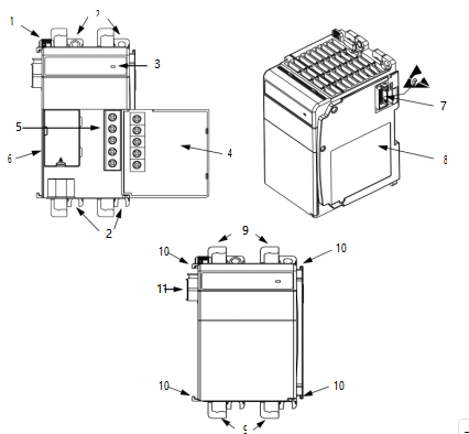
| Item | Description |
| 1 | Bus lever |
| 2 | Upper and lower panel mounting tabs |
| 3 | Status Indicator |
| 4 | Power supply door with terminal identification label |
| 5 | Terminal block with fingersafe cover |
| 6 | Cover for replaceable fuse |
| 7 | Stationary bus connector with male pins |
| 8 | Nameplate label |
| 9 | Upper and lower DIN rail latches |
| 10 | Upper and lower tongue-and-groove slots |
| 11 | Movable bus connector with female pins |
Assemble the System
1769 Compact I/O power supplies distribute power from either side of the power supply.
| EXAMPLE The 2 A at 5V DC power supply (1769-PA2, 1769-PA2K, 1769-PB2, 1769-PB2K) can provide 1 A to the right side of the power supply and 1 A to the left. The 4 A at 5V DC power supply (1769-PA4, 1769-PA4K, 1769-PB4, and 1769-PB4K) can provide 2 A to the right side of the power supply and 2 A to the left. | |||
| The maximum amount of current the system supports in both directions is: • 1769-PA2, 1769-PA2K, 1769-PB2, 1769-PB2K: 2 A at 5V DC; 1 A at 24V DC • 1769-PA4, 1769-PA4K, 1769-PB4, 1769-PB4K: 4 A at 5V DC; 2 A at 24V DC | |||
| IMPORTANT | The maximum amount of current that can be distributed from either side of any 1769 power supply is 2 A at 5V DC and 1 A at 24V DC. This condition is a limit of the 1769 Compact I/O bus. | ||
| The | power supply can | be attached to an adjacent I/O module before or after mounting. | |
| WARNING: If you connect or disconnect wiring while the field-side power is on, an electric arc can occur. This could cause an explosion in hazardous location installations. Be sure that power is removed or the area is nonhazardous before proceeding. | |||
Follow these steps to assemble the Compact I/O system.
- Verify that linepower is disconnected.
The power supply does not support removal or insertion of modules under power.
- Make sure that thebuslever of the power supply is in the unlocked position, that is, fully to the right.
- Use the upper andlower tongue-and-grooveslots to attach the power supply to a controller or I/O module.
- Move thepower supplyback along the tongue-and-groove slots until the bus connectors align with each other.
- Use your fingers or asmallscrewdriver to push the power supply bus lever back slightly to clear the tab position.
- Move thepower supplybus lever fully to the left until it clicks; make sure that it locks.
ATTENTION: When you attach expansion power supplies, it is important that the bus connectors are securely locked together to achieve proper electrical connection.
- To install additionalI/O modules or end caps, refer to their respective installation instructions.
IMPORTANT You must install an end cap onto the right side of the Compact I/O controller system either at the end of the controller or at the end of any local expansion modules that can be installed onto the controller.
The end cap covers the exposed interconnections on the right side of the controller or
module. Failure to use a protective covering could result in equipment damage or injury from electric shock.
Mount the System
You can mount a Compact control system on a DIN rail or on a panel:
- UseEN50 022 – 35 x 7.5 mm (1.38 x 0.30 in.) or EN 50 022 – 35 x 15 mm (1.38 x 0.59 in.) DIN rails.
- Use fourM4or #8 pan head screws for panel-mounting.
| ATTENTION: During panel or DIN rail mounting of all devices, be sure that all debris (such as metal chips or wire strands) is kept from falling into the controller. Debris that falls into the controller could cause damage while the controller is energized. | |
Ground through a DIN Rail | |
| ATTENTION: This product is grounded through the DIN rail to chassis ground. Use zinc-plated chromate-passivated steel DIN rail to assure proper grounding. The use of other DIN rail materials (for example, aluminum or plastic) that can corrode, oxidize, or are poor conductors, can result in improper or intermittent grounding. Secure DIN rail to mounting surface approximately every 200 mm (7.8 in.) and use end-anchors appropriately. Be sure to ground the DIN rail properly. Refer to Industrial Automation Wiring and Grounding Guidelines, Rockwell Automation publication 1770-4.1, for more information. | |
Ground through a Panel | |
| ATTENTION: This product is intended to be mounted to a well-grounded mounting surface such as a Wiring and Grounding Guidelines, Rockwell Automation publication 1770-4.1, for additional information. | |
Panel Mount Template
Minimum Spacing
Maintain spacing from enclosure walls, wireways, adjacent equipment, and so forth. Allow 50 mm (2 in.) of space on all sides for adequate ventilation.
| Item | Description |
| 1 | This device could be an end cap, controller, adapter, or expansion cable depending on your system configuration. |
| 2 | This device could be an end cap or expansion cable depending on your system configuration. |
Prevent Excessive Heat
For most applications, normal convective cooling keeps the system within the specified operating range. Verify that the specified temperature range is maintained. Proper spacing of components within an enclosure is
sufficient for heat dissipation.
In some applications, other equipment inside or outside the enclosure can produce a substantial amount of heat. In this case, place blower fans inside the enclosure to help with air circulation and to reduce hot spots near the system. If additional provisions are necessary to cool high ambient temperatures, follow these guidelines:
- Donot bring in unfiltered outside air.
- Place theCompactI/O system in an enclosure to protect it from a corrosive atmosphere. Harmful contaminants or dirt can cause improper operation or damage components.
- In extremecases,use air conditioning to protect against heat build-up within the enclosure.
Connect the System
Compact I/O system architecture and the power supply design support I/O connection on either side of the power supply. Each I/O bank requires its own power supply.
To connect two I/O banks, attach a 1769 expansion I/O cable to a power supply or I/O module as shown in the
following illustration. Up to 8 I/O modules can be connected on either side of the power supply for a maximum of 16 modules per bank.
Each 1769 I/O module has a power supply distance rating, with a maximum value of eight. See the installation instructions for the specific 1769 I/O module for more information.
Connection Example
2
3
| Item | Description |
| 1, 2 | The maximum amount of bus current that can be distributed on the 1769 bus (on either side of the power supply) is: • 2 A at 5V DC (assume supported by power supply) • 1 A at 24V DC (assume supported by power supply) |
| 3 | Expansion I/O power supplies |
| 4 | I/O communication expansion cable |
IMPORTANT To use a 1769 expansion I/O power supply with a controller that has an embedded power supply
(for example, a MicroLogix™ 1500 controller), you must use a 1769 expansion I/O cable. Do not
directly attach the expansion power supply to a controller that has an embedded power supply.
Wire the Power Supply
2
Connect incoming power to the power supply terminals as
indicated in this table. Connect the ground screw of the
power supply to the nearest ground or ground bus.
To wire the terminal block, use the directions on page 12.
5
| Item | 1769-PA2, 1769-PA2K | 1769-PA4, 1769-PA4K | 1769-PB2, 1769-PB2K, 1769-PB4, 1769-PB4K | ||
| 1 | PWR OUT +24V DC(1) | NOT USED | NOT USED | ||
| 2 | PWR OUT COM(1) | NOT USED | NOT USED | ||
| 3 | 120/240V AC (L1) | 120/240V AC (L1) | +24V DC | ||
| 4 | V AC COM (L2) | V AC COM (L2) | DC NEUTRAL | ||
| 5 | CHASSIS GROUND | CHASSIS GROUND | CHASSIS GROUND | ||
(1) 24V DC user power for sensors or other special 24V DC I/O devices
ATTENTION: This symbol denotes protective earth ground and earth ground terminals that
provide a low impedance path between electrical circuits and earth for safety purposes and provides noise immunity improvements. You must make these connections for safety purposes.
Each terminal accepts as many as two wires with the following restrictions. Keep the leads as short as possible.
| Wire Size | Wire Type | Terminal Screw Torque |
| 2.5 mm2 (14 AWG) Solid | Cu-90 °C (194 °F) | 1.27 N•m (11.24 lb•in) |
Wire the Fingersafe Terminal Block
ATTENTION: Turn off incoming power before connecting or disconnecting wires. Failure to do so could cause injury to personnel and/or damage to equipment.
When wiring the terminal block, keep the fingersafe cover in place.
If you must remove the fingersafe cover, insert a screwdriver into one of the square wiring holes and gently pry the cover off. If you wire the terminal block with the fingersafe cover removed, you cannot put it back on the terminal block because the wires are in the way.
- Loosen the terminal screws.
- Route the wire under the terminalpressureplate.
You can use the bare wire or a spade lug. The terminals accept a 6.35 mm (0.25 in.) spade lug.
The terminal screws are non-captive, so it is possible to use a ring lug. The terminals
minimum inside diameter of 3.5306 mm (0.139 in.) [M3.5].
- Tighten the terminal screw, be sure that thepressureplate secures the wire. The recommended torque is 1.27 N•m (11.24 lb•in).
Replace the Fuse
ATTENTION: Do not remove or replace fuse when energized. Be sure that power is removed before proceeding.
Follow these steps to replace a blown fuse.
- Removepower from the controller system.
- Correct the conditions that caused thefuseto blow.
- Toremove the fusehousing cover, place a slotted screwdriver under the tab.
- Use a fusepuller or similardevice to remove the fuse.
Be careful. Do not damage the printed circuit board and nearby electronics.
- Center thereplacement fuse over the fuseclip and press down.
To determine which fuse type to use, see Specifications on page 14.
If you use a tool to press the fuse in place, apply pressure only to the metal end caps, not to the center of the fuse.
- Replace the fusehousing cover.
- Restorepower to the controller system.
Specifications
| Attribute | 1769-PA2, 1769-PA2K(1) | 1769-PB2, 1769-PB2K | 1769-PA4, 1769-PA4K | 1769-PB4, 1769-PB4K |
| Temperature, operating IEC 60068-2-1 (Test Ad, Operating Cold IEC 60068-2-2 (Test Bd, Operating Dry Heat) IEC 60068-2-14 (Test Nb, Operating Thermal Shock) | 0 °C < Ta < 60 °C (32 °F < Ta < 140 °F) | |||
| Input voltage range | 85…265V AC | 19.2 31.2V DC | 85…265V AC | 19.2 32V DC |
| Input frequency range | 47…63 Hz | N/A | 47…63 Hz | N/A |
| Isolation voltage | 265V (continuous), Reinforced Insulation Type Routine tested at 2596V DC for 1 s, AC Power Input to System and AC Power Input to 24V DC User Power | 75V (continuous), Reinforced Insulation Type Routine tested at 1697V DC for 1 s, DC Power Input to System | 265V (continuous), Reinforced Insulation Type (IEC Class 1 grounding required) Routine tested at 2596V DC for 1 s, AC Power Input to System | 75V (continuous), Reinforced Insulation Type (IEC Class 1 grounding required) Routine tested at 1697V DC for 1 s, DC Power Input to System |
| Current capacity @ 5V DC | 2.0 A | 2.0 A | 4.0 A | 4.0 A |
| Current capacity @ 24V DC | 0.8 A | 0.8 A | 2.0 A | 2.0 A |
| Fuse type | Littelfuse 02153.15MXP | Littelfuse 021706.3MXP | Littelfuse 02183.15MXP | Littelfuse 0217008.MXP |
| Wire size | 2.5 mm2 (14 AWG) solid copper wire rated at 90 °C (194 °F), or greater, 1.2 mm (3/64 in.) insulation max | |||
| North American temp code | T3C | |||
| UKEX/ATEX/IECEx temp code | N/A | T4 | N/A | T4 |
| Enclosure type rating | None (open-style) | |||
(1) Catalog numbers followed by a“K”indicate a conformal coating option.
Additional Resources
These documents contain additional information concerning related products from Rockwell Automation.
| Resource | Description |
| CompactLogix Power Supplies Specifications Technical Data, publication 1769-TD008 | Provides a detailed description of the 1769 CompactLogix™ and Compact I/O power supplies. |
| MicroLogix 1500 Programmable Controllers User Manual, publication 1764-UM001 | Provides information on how to install and use your Compact I/O with the MicroLogix 1500 programmable controller. |
| Industrial Automation Wiring and Grounding Guidelines, publication 1770-4.1 | Provides general guidelines for installing a Rockwell Automation industrial system. |
| Product Certifications website, | Provides declarations of conformity, certificates, and other certification details. |
Rockwell Automation Support
Use these resources to access support information.
| Technical Support Center | Find help with how-to videos, FAQs, chat, user forums, and product notification updates. | rok.auto/support |
| Knowledgebase | Access Knowledgebase articles. | rok.auto/knowledgebase |
| Local Technical Support Phone Numbers | Locate the telephone number for your country. | rok.auto/phonesupport |
| Literature Library | Find installation instructions, manuals, brochures, and technical data publications. | rok.auto/literature |
| Product Compatibility and Download Center (PCDC) | Download firmware, associated files (such as AOP, EDS, and DTM), and access product release notes. | rok.auto/pcdc |
Documentation Feedback
Your comments help us serve your documentation needs better. If you have any suggestions on how to improve
our content, complete the form at rok.auto/docfeedback.
Waste Electrical and Electronic Equipment (WEEE)
At the end of life, this equipment should be collected separately from any unsorted municipal waste.
Rockwell Automation maintains current product environmental compliance information on its website at rok.auto/pec.
Rockwell Otomasyon Ticaret A.Ş. Kar Plaza İş Merkezi E Blok Kat:6 34752, İçerenköy, İstanbul, Tel: +90 (216) 5698400 EEE Yönetmeliğine Uygundur
rckwe lautomation · Cm epandng human poss· b· · ty
AMERICAS: Rockwell Automation , 1201 south second street , Milwaukee , WI 53204 – 2496 USA, Tel : (1)414 . 382 . 2000 , Fax: (1)414 . 382 . 4444
EUROPE/MDDLE EAST/AFRCA: Rockwell Automation NV, pegasus park, De kleetlaan 12a , 1831 Diegem , Belgium , Tel : (32)2 663 0600 , Fax: (32)2 663 0640
ASIA PACIFlc: Rockwell Automation , Level 14 , core F, cyberport 3 , 100 cyberport Road , Hong kong , Tel : (852)28874788 , Fax: (852)2508 1846
Allen-Bradley, Compact I/O, CompactLogix, expanding human possibility, MicroLogix, and Rockwell Automation are trademarks of Rockwell Automation, Inc.
Trademarks not belonging to Rockwell Automation are property of their respective companies.
Publication 1769-IN028J-EN-P – August 2022 | Supersedes 1769-IN028I-EN-P – July 2020 PN-674430
Copyright © 2022 Rockwell Automation, Inc. All rights reserved. Printed in the U.S.A.